Title here
Summary here
IMUs
IMU stands for Inertial Measurement Unit. While a motor encoder tells you how far the wheels have spun, an IMU tells you something different — which direction the robot is facing, whether it is turning, and if it is about to tip over.
In VEX Robotics, the V5 Inertial Sensor packs two sensors into one small device: a gyroscope and an accelerometer.
Why does this matter?
An IMU is essential for autonomous driving. Knowing if your robot is pointing straight vs. slightly crooked can be the difference between scoring a point and missing completely. It also helps with safety — detecting if the robot is tilting over before a disaster happens!
How it Works
Inside the IMU is a tiny chip called a MEMS sensor (Micro-Electro-Mechanical Systems). This chip has microscopic physical structures inside that flex and move when the robot moves. It is almost like a tiny version of an amusement park ride sensor!
The IMU contains two types of sensors working together:
Accelerometer (measures straight-line movement): Detects how quickly the robot speeds up or slows down in a straight line. Since gravity is a constant downward force, the accelerometer can also always tell which direction is “down,” helping the robot detect tilting.
Gyroscope (measures rotation): Detects how fast the robot is twisting or spinning. This is what lets your robot know if it has turned exactly 90 degrees during autonomous.
Together, these two sensors update many times per second to track the robot’s orientation in 3D space.
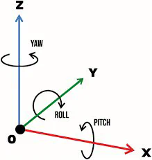
The 3 Axes of Rotation
Pilots and aircraft engineers came up with the terms we use to describe rotation in 3D space. Robots use the same three terms:
Advanced Math (For Curious Teams)
The IMU’s accelerometer can theoretically calculate position without wheel encoders. Here is the basic idea:
Warning: While this math works in theory, in practice tiny errors in the accelerometer data add up very quickly. After just a few seconds, the calculated position can be noticeably wrong. For best results, use wheel encoders for distance and the IMU only for heading (Yaw).
Best Practices