Title here
Summary here
Gear Ratios
Motors are powerful, but they do not always spin at exactly the right speed or with exactly the right strength for every task. That is where gears come in!
A gear ratio describes the relationship between two or more gears that are connected together. Mastering gear ratios is the secret to building fast drivetrains, powerful lifting arms, and reliable intakes without burning out your motors.
Why does this matter?
A robot that drives fast might not be able to lift heavy objects, and a robot that lifts heavy objects might not drive very fast. Gear ratios are how you tune that balance for whatever your robot needs to do.
Speed vs. Torque
Every motor has a fixed amount of total power. You can think of it like a budget — you can spend it on speed or on strength, but not both at the same time.
The Golden Rule: If you want more speed, you lose torque. If you want more torque, you lose speed. You cannot have both at once.
When two gears connect, each plays a role:
Calculating a Gear Ratio
To find the gear ratio, divide the number of teeth on the driven (output) gear by the number of teeth on the driving (input) gear:
$$ \text{Gear Ratio} = \frac{\text{Teeth on Driven Gear (Output)}}{\text{Teeth on Driving Gear (Input)}} $$Examples
Imagine two gears: one with 42 teeth (on the motor) and one with 14 teeth (on the wheel).
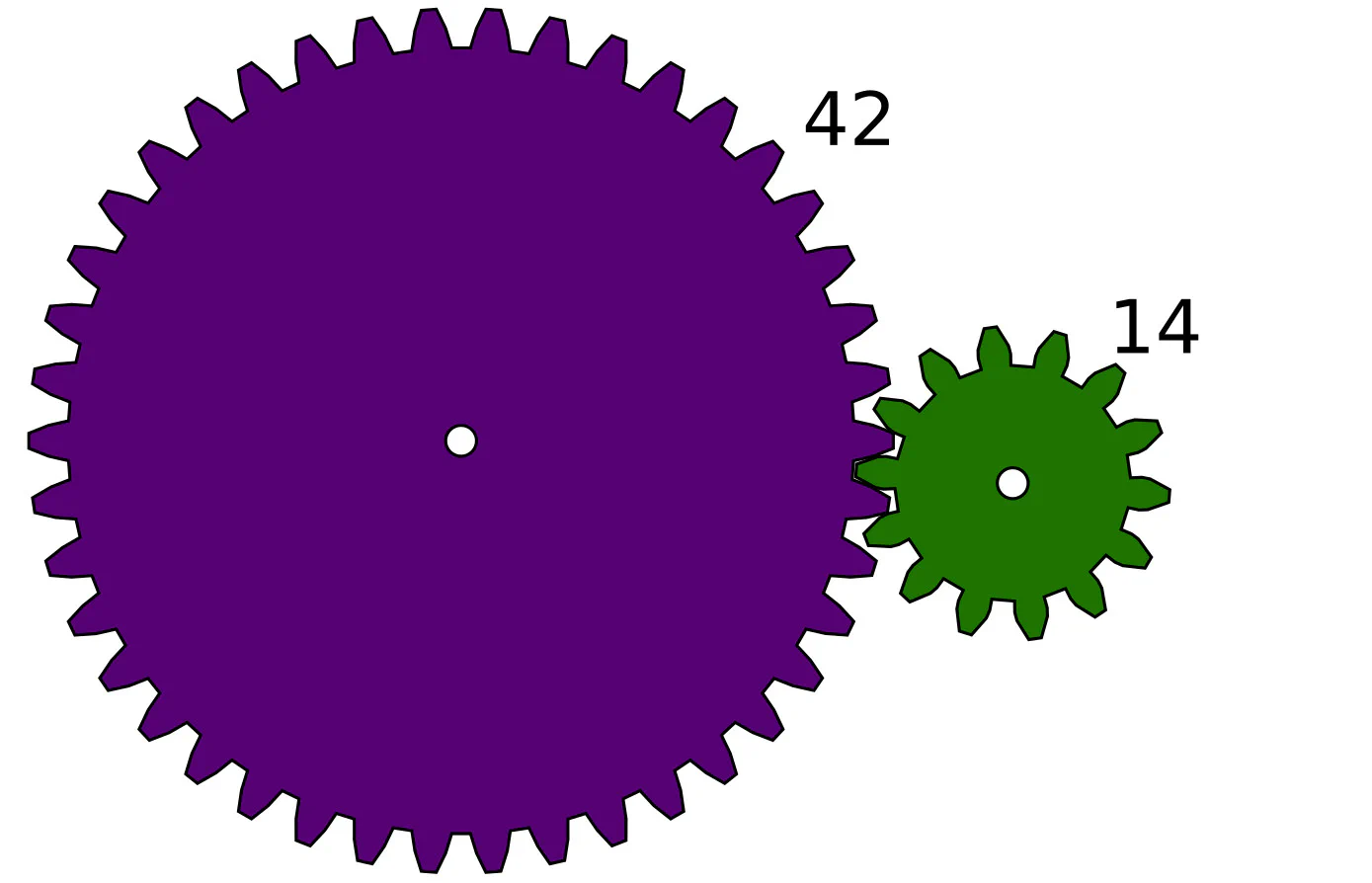
Now swap the roles — the 14-tooth gear is on the motor and the 42-tooth gear is on the mechanism:
$$ \text{Gear Ratio} = \frac{42}{14} = \frac{3}{1} \rightarrow 3:1 $$Idler Gears
An idler gear is a third gear placed in between the driving and driven gears.
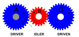
Surprisingly, idler gears do NOT change the gear ratio at all. So why use them?
Compound Gear Trains
Sometimes a simple two-gear system cannot give you enough of a ratio without needing enormous gears. The solution is a compound gear train — a chain of multiple gear pairs stacked together, each adding more mechanical advantage.
A compound gear train works by locking pairs of gears on the same axle. The first pair gives you one ratio, and the second pair multiplies on top of that.
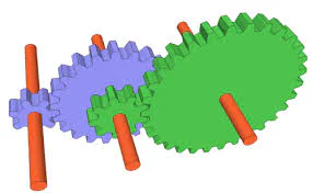
To calculate a compound gear ratio:
Connection to Code
Here is an important detail: your Motor Encoders only measure how much the motor shaft spins — not how much the actual mechanism moves. If you have a 5:1 gear reduction on a lifting arm and you want the arm to raise 90 degrees, you need to tell the motor to spin 5 times as much:
$$\text{Motor Target} = 90^\circ \times 5 = 450^\circ$$Always account for your gear ratio in your code, or your movements will be way off!